Diamond’s Digital I/O module family includes a wide range of rugged, wide-temperature PC/104, PC/104-Plus, PCIe MiniCard, and FeaturePak modules featuring programmable bi-directional digital I/O, counter/timers, optoisolated inputs, and relay outputs.
Digital I/O |
Counter/Timers |
Misc. |
|||||||||
Product |
Form Factor |
# I/O |
Buf |
Prog |
Optos |
Relays |
# Ctrs |
Res |
Max |
IRQ |
XT |
OMM-XT |
PC/104 |
48 I/O |
Yes |
3 |
10MHz |
3 |
Yes |
||||
OMM-DIO-XT |
PC/104 |
48 I/O |
Yes |
Yes |
|||||||
PMM-P |
PC/104 |
16 |
Yes |
||||||||
OPMM-1616-XT |
PC/104 |
16 |
16 |
Yes |
|||||||
IR104-PBF |
PC/104 |
20 |
20 |
||||||||
GPIO-MM |
PC/104 |
48 I/O |
Yes |
10 |
16 |
40MHz |
Yes |
||||
GPIO-MM-12 |
PC/104 |
48 I/O |
Yes |
10 |
16 |
40MHz |
Yes |
||||
GPIO-MM-21 |
PC/104 |
48 I/O |
Yes |
10 |
16 |
40MHz |
Yes |
||||
P104-GPIO96 |
PC/104-Plus |
96 I/O |
Yes |
Yes |
8 |
32 |
Yes |
||||
DS-MPE-GPIO |
PCIe MiniCard |
36 I/O |
Yes |
4 |
32 |
Yes |
|||||
FP-GPIO96 |
FeaturePak |
96 I/O |
Yes |
Yes |
8 |
32 |
Yes |
||||
LegendI/O Programmable directionHeadingsBuf Buffered outputs Prog Prog. direction Res Resolution Max Max clock input rate IRQ Interrupt outputs XT -40 to +85 degrees C |
|||||||||||
Produtos
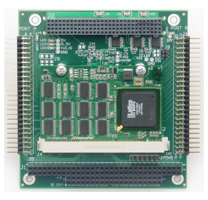
GPIO-MM Digital I/O Module
PC/104
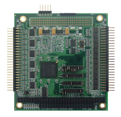
GPIO-MM is a PC/104 digital I/O module based on an FPGA, allowing multiple feature sets to be implemented on the same hardware platform. The FPGA is a Xilinx Spartan 2 RAM-based device with 200K gates (XC2S200). An on-board configuraton flash memory device stores the FPGA code for automatic loading on power-up, and new code can be downloaded using a JTAG cable connected to a PC. Several standard off the shelf personalities are available, and custom ones can be developed either by users with Xilinx tools or by Diamond as a customization service.
The right side I/O connector includes ESD protection circuitry for increased reliability, while the left side I/O connector offers high-drive logic buffers for increased load compatibility, along with jumper-configured pull-up / pull-down resistors. All digital I/O pins are set to input on power-up to avoid conflicts with external circuitry.
Informações extras
Hardware configuration options include jumper-selectable base address and DMA level, plus a 10-position jumper lock for user-definable field configurability when used with custom designs. A 256-byte EEPROM provides convenient non-volatile storage for user-defined functionality. The board also includes the layout for an optional RS-232/422/485 serial port, so that a multi-protocol serial port can be integrated into custom designs.
GPIO-MM contains 8 diagnostic LEDs located in the lower left corner. Off-the-shelf configurations use these LEDs to identify the personality programmed onto the board, while custom designs can use them for any purpose. An additional programmable LED in the lower right corner offers a simple way to verify successful FPGA programming.
Standard feature sets include:
- 10 “9513” style 16-bit counter/timers + 8 fixed digital inputs + 8 fixed digital outputs + 48 buffered programmable digital I/O
- 48 programmable digital I/O + 48 buffered programmable digital I/O
9513 Counter/Tmers
The GPIO-MM code includes two 9513 counter/timer cores, each containing 5 16-bit counters. This core is based on the popular high performance AMD9513 counter/timer IC. These counters offer extreme flexibility, with programmable input sources, programmable output waveforms, programmable up / down count, one-shot vs. continuous counting, PWM function, and more. Counters can be cascaded together to form 32-bit, 48-bit, etc. wide counters. An input clock of 40MHz provides fine resolution for timing applications.
GPIO-MM-12 Digital I/O Module
PC/104
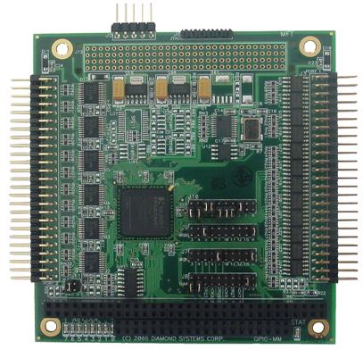
GPIO-MM-12 is part of a family of reconfigurable digital I/O and counter / timer modules with various port and pin configurations. Each board uses identical hardware with a 200K gate Xilinx Spartan II RAM-based FPGA. The varying configurations are based on different FPGA code. The FPGA code is stored in a flash memory on the board, enabling GPIO-MM-12 to be reprogrammed in the field with different designs, including custom designs.
The GPIO-MM-12 configuration provides 48 digital I/O lines and 10 programmable counter/timers. The counter/timer features are based on our legacy Quartz-MM board, while the 48 digital I/O lines are compatible with our legacy Garnet-MM board. This configuration combines the features of both these boards into one board to reduce your PC/104 stack size and cost.
Other GPIO-MM configurations provide up to 96 digital I/O lines.
Informações extras
Counter/Timer Features
The 10 16-bit counter/timers are provided by two 9513 cores. The high speed FPGA enables a fast 40MHz clock input, providing greater precision in timing applications. The counters can be joined under software control to provide 32-bit, 48-bit or 64-bit counters. A variety of input, gate, and output features are available to implement a wide range of waveform, counting, and timing functions. The counter / timer I/O connector uses the same pinout as the connector for Quartz-MM 10-channel boards and includes 16 digital I/O lines configured as 8 inputs and 8 outputs. The fixed I/O and the counter/timer signals feature ESD-protective circuitry.
Digital I/O Features
The digital I/O includes 48 programmable-direction lines using two 8255 cores. All I/O lines are buffered for enhanced output current. All I/O lines contain jumper-selectable 10Kohm pull-up/pull-down resistors. The 48 I/O lines are contained on a single 50-pin connector, along with system ground and a convenient +5V power pin. The I/O connector presents the digital I/O lines in ABC port order.
ISA Bus Interrupts
GPIO-MM-12 offers two user-programmable interrupt circuits. Possible uses include timer based interrupts or interrupts driven by external signals.
Miscellaneous Features
GPIO-MM-12 includes a 256-byte EEPROM for general-purpose non-volatile storage of user application data. Easy register-level access to the EEPROM simplifies use of this valuable feature.
The board requires only a +5V input and operates from -40°C to +85°C. All board functions are supported by our Universal Driver software for Linux, Windows 2000/XP/CE, DOS, and QNX.
GPIO-MM-21 Digital I/O Module
PC/104
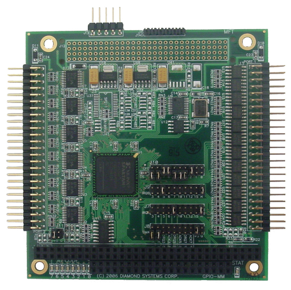
GPIO-MM-21 is part of a family of reconfigurable digital I/O and counter / timer modules with various port and pin configurations. Each board uses identical hardware with a 200K gate Xilinx Spartan II RAM-based FPGA. The varying configurations are based on different FPGA code. The FPGA code is stored in a flash memory on the board, enabling GPIO-MM-21 to be reprogrammed in the field with different designs, including custom designs.
The GPIO-MM-21 configuration provides 96 digital I/O lines. 48 lines are buffered. The 96 digital I/O lines are compatible with our legacy Garnet-MM and Onyx-MM boards. This configuration combines the features of two 48-line digital I/O boards into one board to reduce your PC/104 stack size and cost.
Other GPIO-MM configurations provide 48 digital I/O lines with 10 16-bit counter/timers.
Digital I/O Features
The digital I/O includes 96 programmable-direction lines using four 8255 cores. 48 of the I/O lines are buffered for enhanced output current. All I/O lines contain jumper-selectable 10Kohm pull-up/pull-down resistors. 48 I/O lines are contained on each of two 50-pin connectors, along with system ground and a convenient +5V power pin. Both I/O connectors provide the digital I/O lines in ABC port order.
Miscellaneous Features
The board requires only a +5V input and operates from -40°C to +85°C. All board functions are supported by our Universal Driver software for Linux, Windows 2000/XP/CE, DOS, and QNX.
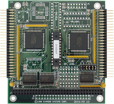
Onyx-MM Digital I/O Module
PC/104
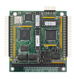
Extensive software control of features is the highlight of this digital I/O module featuring 48 digital I/O lines, 3 16-bit counter/timers, and 3 independent PC bus interrupt inputs.
The 48 digital I/O lines on Onyx-MM are based on 2 82C55 ICs. They can be programmed for input or output in groups of 8 lines. Direct as well as strobed (latched) I/O modes are supported, and all I/O lines are connected to 10K Ohm pull-up resistors.
The 3 16-bit counter/timers are based on an 82C54 IC. They are controlled through a configuration register on Onyx-MM (in addition to the standard 82C54 configuration register). The counter inputs can be switched between external signals, the on-board 4MHz clock oscillator, or counter outputs, all under software control. By using one counter’s output as another counter’s input, you can cascade counters in software to create a 32-bit or 48-bit counter.
Onyx-MM also features programmable interrupt operations. A second software-controlled register on board configures up to 3 interrupt lines on the PC bus. Interrupts can be generated by the counter/timer outputs, digital I/O lines, or an external input line. This allows you to use a counter to generate bus interrupts at a programmed periodic rate, generate hardware interrupts under software control, or generate interrupts in response to an external event.
Onyx-MM-DIO Digital I/O Module
PC/104
DIf you’re looking for a basic 48-line digital I/O PC/104 module, then Onyx-MM-DIO is what you need. This module is the same as our Onyx-MM digital & counter/timer module but without the counter/timer and interrupt circuitry. This board still has the quality and attention to detail of our other modules, such as: 10K Ohm pull-up resistors on all I/O lines; all ports reset to 0 on power-up or system reset; connector pinouts compatible with our other digital I/O boards; and free software.
The 48 digital I/O lines on Onyx-MM-DIO are based on 2 82C55 ICs. They can be programmed for input or output in groups of 8 lines. Direct as well as strobed (latched) I/O modes are supported, and all I/O lines are connected to 10K Ohm pull-up resistors.
Opal-MM-1616 Opto In + Relay Out Module
PC/104
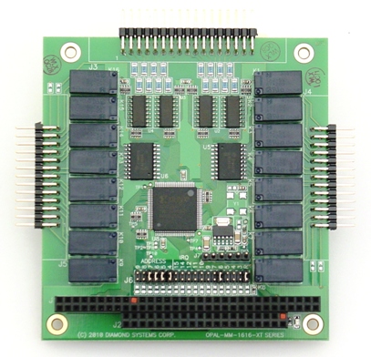
Opal-MM-1616 is a PC/104 format digital I/O module designed for industrial applications requiring isolation between the computer and the external signals it is monitoring and controlling.
The Opal-MM-1616 features 16 optoisolated digital inputs and 16 relay outputs. Each input has an input range of 0-30VDC. Opal-MM-1616 can be configured to generate an interrupt when any input changes state. Either or both banks of 8 inputs can be configured for interrupt operation. One 34-pin I/O header is used for the optoisolated inputs.
The 16 relay outputs are SPDT format (form C). Each relay has 3 contacts: Common, Normally Open, and Normally Closed. For safety and reliability, all relays are at their power-off state at power-up or system reset. Each relay can switch both AC and DC voltages. Two 26-pin I/O headers are used for the relay outputs with 8 relays on each pin header. The relays have long lifetime (10,000,000 operations) and quick actuation time (5ms max operate and release, break before make).
Diamond Systems’ Universal Driver software provides drivers and example code for use with the Opal-MM-1616. The software provides support for interrupts and enables you to integrate you own code that is called when an interrupt occurs.
Pearl-MM Relay Output Module
PC/104
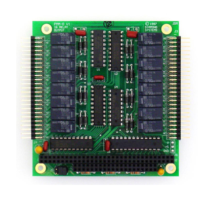
Pearl-MM is a PC/104 format industrial control module with 16 relays. The relays have PDT (form C) configuration. Each relay has 3 contacts: Common, Normally Open, and Normally Closed. For safety and reliability, all relays are in their power-off state (Common connected to Normally Closed) at power-up or system reset. The relays can switch both AC and DC voltages. They feature long life (100,000,000 operations), quick actuation time (4ms max operate and release), and isolation (500V AC or DC).
IR104-PBF Opto In & Relay Out Module
PC/104
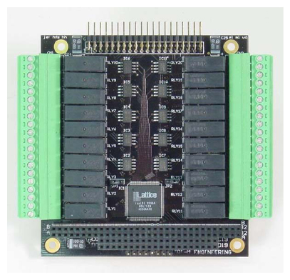
IR104-PBF is a high-density PC/104 format digital I/O module designed for industrial applications requiring isolation between the computer and the external signals it is monitoring and controlling. This module features 20 optoisolated digital inputs and 20 relay outputs. Each input can accept both AC and DC voltages as low as 3V and as high as 24V.
The optocoupler inputs are located on a pin header at the top of the board, while the relays feature quick-disconnect terminal blocks (10 relays per block) that accept wire ranging from 14-28AWG. The board will operate in ambient temperatures ranging from -25 to +70C.
Note: The maximum component height on this board is .492″, slightly higher than the PC/104 standard of .435″. This extra height will usually not be a problem unless the board stacked directly above the IR104-PBF has components mounted on the bottom of the board or through-hole pins that exceed .043″ in height. In this case you can mount the IR-104-PBF on the top of the stack.
Output Relays
The 20 relay outputs have SPST (form A) normally open contacts. Each relay can switch both AC and DC voltages. The relays have long lifetime (20,000,000 operations, 100,000 at full load) and quick actuation time (6ms max operate, 3ms release).Maximum load is 5A @30VDC. Relay connections are made with detachable screw terminal blocks. Each of the 2 blocks carries contacts for 10 relays.
Input Optoisolators
The 20 optoisolators can accept either AC or DC inputs ranging from 3V to 24V. Opto input connections are made with a 40-pin pin header that mates with standard ribbon cables.
P104-GPIO96 Digital I/O Module
PC/104-Plus
P104-GPIO96 is a PC/104-Plus general purpose digital I/O module integrating Diamond’s using a high-capacity PCI Express FPGA for maximum density and flexibility.
P104-GPIO96 is a programmable PCI-104 DIO module using a high-capacity (700K gate equivalent) PCI Express FPGA for maximum density and flexibility. The base hardware configuration features 96 digital I/O lines grouped into 12 8-bit ports. All ports have I/O buffers to protect the FPGA and feature 5V logic drive levels. The ports are organized into a combination of byte-wide, nibble-wide, and bit-wide direction control for maximum flexibility and application compatibility.
The built-in FPGA personality provides multiple configuration options. All 96 I/O lines may be used in common I/O mode; Six of these ports can be reconfigured to enable an array of additional features, including 8 32-bit up/down counter/timers with programmable input source and gate, 4 24-bit PWM circuits with 0-100% duty cycle capability and interrupt/latched mode operation.
The flash-based design enables easy field upgrades using a Diamond-provided software utility (no cable or third-party software required!) as well as custom code development. Universal Driver software support (described below) is included for Linux, Windows XP, Windows Embedded CE/Standard.
DS-MPE-GPIO Digital I/O Module
PCIe MiniCard
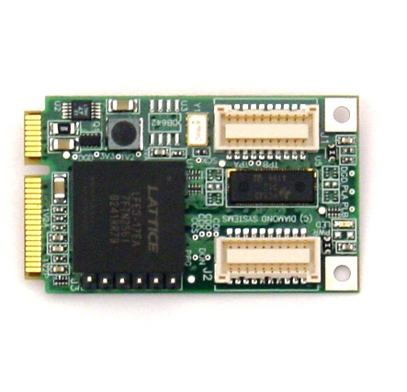
The DS-MPE-GPIO is a rugged, low cost 36-channel digital I/O PCIe MiniCard module that is ideal for digital I/O expansion in embedded and OEM applications.
An FPGA provides 36 buffered digital I/O lines that can be configured to operate in simple I/O mode in the form of 8-bit and 4-bit ports, or in counter/timer and pulse width modulator modes. Two ports are fixed digital I/O ports with programmable direction in 8-bit groups. One port can operate as either a 4-bit DIO or 4 counter/timers with 1 input and 1 output per counter. One port can operate as either 8 DIO or up to 8 pulse width modulators.
Extended temperature operation of -40°C to +85°C enables the board to operate in environments with extreme temperature swings, such as vehicles or outdoor installations.
The DS-MPE-GPIO product comes with the 36-channel PCIe MiniCard digital I/O module, the CK-DAQ02 cable kit with two digital I/O cables, and a hardware kit with mounting screws.
FP-GPIO96 Digital I/O Module
FeaturePak
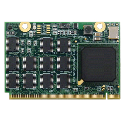
FP-GPIO96 is a general purpose I/O FeaturePak module using a high-capacity (700K gate equivalent) PCI Express FPGA for maximum density and flexibility. The base hardware configuration features 96 digital I/O lines grouped into 12 8-bit ports. All ports have I/O buffers to protect the FPGA and feature 5V logic drive levels. The ports are organized into a combination of byte-wide, nibble-wide, and bit-wide direction control for maximum flexibility and application compatibility.
The built-in FPGA personality provides multiple configuration options. All 96 I/O lines may be used in common I/O mode; Six of these ports can be reconfigured to enable an array of additional features, including 8 32-bit up/down counter/timers with programmable input source and gate, 4 24-bit PWM circuits with 0-100% duty cycle capability and interrupt/latched mode operation.
The flash-based design enables easy field upgrades using a Diamond-provided software utility (no cable or third-party software required!) as well as custom code development. Universal Driver software support (described below) is included for Linux, Windows XP, Windows Embedded CE/Standard.
Baixe Nosso Catálogo
Acesse nosso catálogo resumido de
produtos e todas as marcas que representamos!
Fale Conosco
bl@blbrasil.com.br | 11 3667-6013
